
Front right : B, W (black, white)
Front left : G, R (green, red)
Rear left : L, p (blue, pink)
Rear right : Y, BR (yellow, brown)
- In the ABS wheel sensor what is the reason for the braided wire?
Reduce electrical noise and preventing other signals coming in which influences ABS's wrong operation.
- Identify and list all the fuses that are used by the ABS circuit.
FL MAIN, F14 50A ABS, 10A gauge, 20A DONE, 15A STOP and 15A ECU-IG
- Identify the earths for the ABS control unit and ABS motor their wire colours what pins numbers.
ABS ECU : W/B(white and black) 10B, 7B
ABS Motor : W/B(white and black) 1A
- The wire colours and pin numbers of Solenoids control
Front Right Wheel
Pin number : 2B, 6B
wire colours : R/W(red and white), R/G(red and green)
Front Left Wheel
Pin number : 3B, 7B
wire colours : L/R(blue and red), L/W(blue and white)Rear Right Wheel
Pin number : 1B, 5B
wire colours : BR/W(brown and white), BR/R(brown and red)
Rear Left Wheel
Pin number : 4B, 8B
wire colours : G/B(green and black), G/Y(green and yellow)

Inlet valve open, Outlet valve close
Without ABS operation, the brake pressure of a master cylinder will directly go through inlet valves and brake calipers.
- To reduce wheel brake pressure
Inlet valve close, Outlet valve open
In this case, the ABS is operating. The brake pressure of a master cylinder will go through the pump and outlet valves. At the same time, the check valves are opened therefore the pressure will be reduced in brake lines.
- To hold wheel brake pressure
Inlet valve close, Outlet valve close
When both Inlet valve and outlet valve are closed, the brake pressure is constantly held in the brake lines.
- To increase wheel brake pressure
Inlet valve open, Outlet valve close
In this case, the ABS is operating. the brake pressure flows similar to the normal braking and additionally higher pressure is produced by an ABS motor and this high pressure will strongly hold the wheels.
- The ABS motor's working
Both reducing wheel brake pressure and increasing wheel brake pressure
- Digital signal 5v every 2seconds

- Analogue signal 0.5Hz and a maximum of +3v

2. ABS Demonstrators
Left front ECU Pin # 4 and 5
Left rear ECU Pin # 7 and 9
Right front ECU Pin # 11 and 21
Right rear ECU Pin # 24 and 26
Inductive or magnetic sensor
I have used the AC range of a scope.

- Waveform
Left front


All the waveforms are not exactly the same. Because there are different gap size between speed sensor and teeth of wheels.
- AC volts
Left front : 3.2v
Left rear : 4.09v
Right front : 2.79v
Right rear : 2.89v
I have check the frequency with the graph from the scope.
We can not see both voltage and time from the multi meter. So, the oscilloscope is more accurate.
3. ABS Relays
Powers up the ABS pump : K100
sends power to the ABS HCU solenoids : K38
What is the ECU pin number for the wire that brings in the power to the ABS ECU?
Pin# 1
For the wire that controls the relay for the ABS ECU?
Pin# 15 (ignition switch-ignition on)
Brings in the power to the ABS Pump?
Pin# 13 (from the actuator)
For the wire that controls the relay for the ABS Pump?
Pin# 28(from the ECU)
-Relay waveform

2. ECU is earth(triggering)
3. ECU is not triggering4. Switch off (power off)
- ABS Pump Relay waveform


On vehicle testing
MAZDA FAMILIA 1998
The vehicle is safely located on the left.
Checking the ABS systems (Wheel speed sensors, ABS control unit, ABS modulator, ABS pump motor, parking brake switch, brake master cylinder, brake fluid level switch, RPM sensor, foot brake switch, brake booster and main ABS control unit fuse.
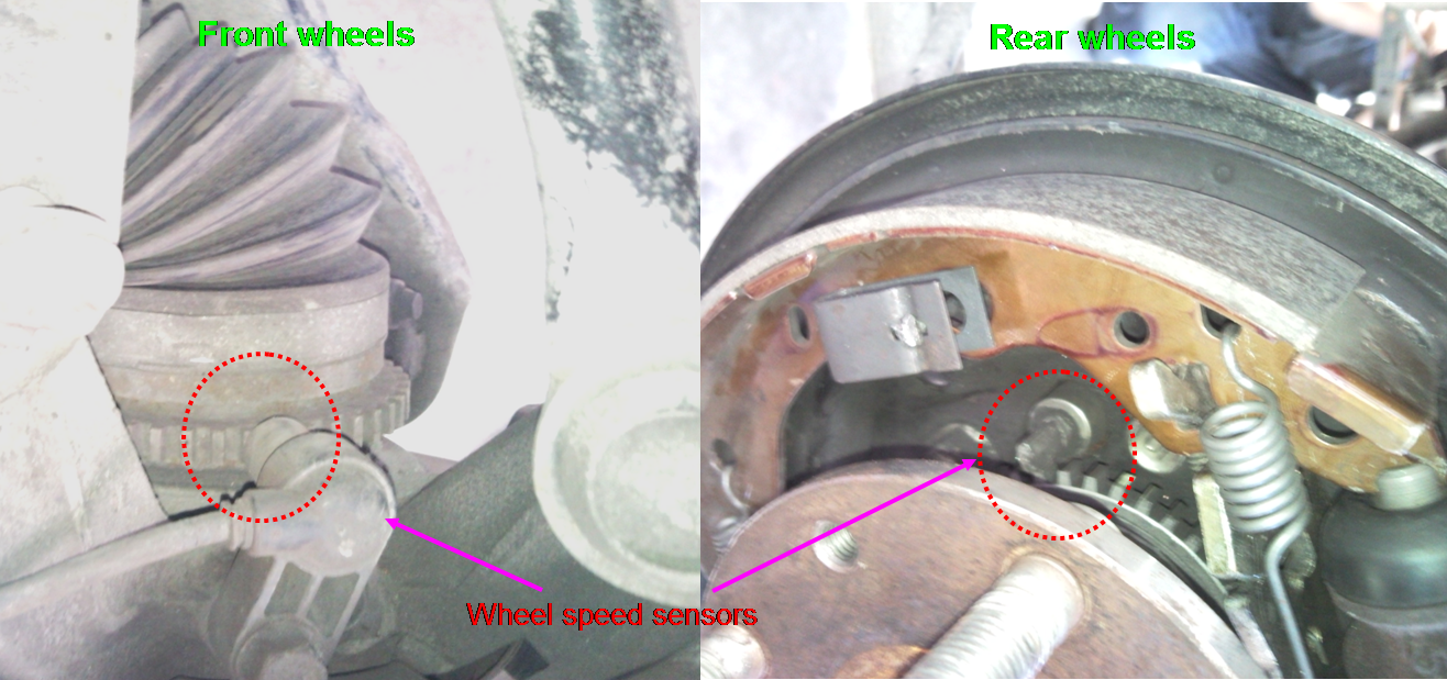
1. Wheel speed sensors Analogue, Magnetic pick up
- Measuring the air gap (Specification 0.4~1.0mm)
Front Right : 0.406mm Good condition
Front Left : 0.660mm Good condition
Rear Right : 0.406mm Good condition
Rear Left : 0.558mm Good condition
- The waveform of a wheel speed sensor

This wheel speed sensor has an analogue pattern.
- Frequency
82Hz (idle, the front wheels turn freely on the lift)

- Using a scan tool
I have hooked up the scan tools on the car with using a correct connector of OBD1. Then, I have selected the ABS scan from scan tool's menu.
Checking live data

I have found some fault codes and problems from the scan tools.
The ABS warning light was turned on due to I have done test ABS speed sensors with dismantling wheels.
The ABS warning light have turned off after I have cleared the codes, installed wheels and moved the vehicle.

Very good so far Kim, just check your answer/waveform for the "Analogue signal 0.5Hz and a maximum of +3v" question.
ReplyDelete