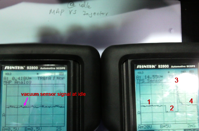
Signal Name : MAP/INJECTORS
Volt/division/range : MAP 0.5v/INJECTORS 20v
Time/division/range :MAP 2S/INJECTORS 2mS
Draw the pattern below:
(Use arrows at different points, and describe what happens there)
When the engine is running at idle, the sensor signal is produced at around 0.4v. At the same time, fuel is injected consistently for the proper combustion of the engine idling.
1. 13v or 14v Supply voltage flows the injector circuit.
2. Fuel injection time. The fuel is injected the combustion chamber with grounding which is at around 2.5ms at idle and the voltage will be at 0v.
3. Peak Voltage. When the magnetic field is collapsed at the injector coil, the high voltage produces at this point.
4. The peak voltage is recovered normal supply voltage.
When the sudden accelerations and opening throttle are added, the vacuum will decrease at the intake manifold with high voltage signals. At the same time, 2 fuel injection time will increase at the injector pattern.
2. RPM (Hall digital crank or distributor) against Injectors(petrol)
Signal Name : RPM/INJECTORS
Volt/division/range : RPM 5ACv/INJECTORS 20v
Time/division/range : RPM 2mS/INJECTORS 2mS
Draw the pattern below:

(Use arrows at different points, and describe what happens there)
When the engine is running at idle, the sensor signal is produced at around 5ACv and its frequency. At the same time, fuel is injected consistently for the proper combustion of the engine idling. As a result, 1 cycle of the RPM sensor is similar to the fuel injection time
When the sudden accelerations and opening throttle are added, the frequency and voltage will increase from the RPM sensor signals. At the same time, the fuel injection time will also increase at the injector pattern.
3. Oxgen sensor against Injectors(petrol)
Signal Name : O2sensor/INJECTORS
Volt/division/range : O2sensor 0.5v/INJECTORS 20v
Time/division/range : O2sensor 5S/INJECTORS 2mS
Draw the pattern below:

(Use arrows at different points, and describe what happens there)
When the engine is running at idle, the O2 sensor signal has costant cycles of Lean and Rich which mean that O2 sensor is well operating with its corrct voltage from 0.2 to 0.8v. At the same time, fuel is injected consistently for the proper combustion of the engine idling at around 2.5mS. When the engine is cold or starting, the O2 sensor signal is not correct. So, I waited for O2 sensor's operating temperature then, I got correct results, such as wave form and signal voltages.
When the sudden accelerations and opening throttle are added, the signal voltage will increase to around 0.8v which means that the fuel is injected the Rich mixture for acceleration and more power. At the same time, the fuel injection time will also increase at the injector pattern, because more fuel comes in the combustion chamber.
4.Injectors(petrol) against Ignition primary
Signal Name : INJECTORS/Ignition Primary
Volt/division/range : INJECTORS 20v /Ignition Primary 20v
Time/division/range : INJECTORS 10mS/Ignition Primary 20mS
Draw the pattern below:

(Use arrows at different points, and describe what happens there)
When the engine is running at idle, the ignition primary has constant frequency. At the same time, fuel is injected consistently for the proper combustion of the engine idling.
From the ingition Primary
1. Supply voltage of 13.6v
2. Dwell time : This is where the coil is actually turned on by the vehicle's control module. The coil is building up a strong magnetic field to spark the spark plug during this part of the pattern.
3. Peak voltage : The coil's earth is removed and the magnetic field or flux collapses across the coils 250 to 350 primary windings, which in turn induces a voltage of 150 to 350 volts.
4.Isolation : This is the part where the coil is turned off and the magnecit field that the coil has generated is now collapsing. You can get an idea what shape your coil is in by watching the isolations just after the spark plug is done firing.
If there are fewer than four isolations at this part of the pattern then there could be some shorting in the coil.
When the sudden accelerations and opening throttle are added, the frequency of the Ignition Primary will increase. At the same time, the fuel injection time will also goes up at the injector pattern.
5.Injectors(petrol) against Ignition primary
Signal Name : Ignition Primary Current/Ignition Primary
Volt/division/range : Ignition Primary Current/Ignition Primary 20v
Time/division/range : Ignition Primary Current 20mS/Ignition Primary 20mS
Draw the pattern below:

(Use arrows at different points, and describe what happens there) When the engine is running at idle, the ignition primary has constant frequency. At the same time, the Ignition Primary Current also has same frequency.
1. no current
2. high current
3. recovered no current
The current switches on as the dwell period starts and rises until the requisite certain amps is achieved within the primary circuit, at which point the current is maintained until it is released at the point of ignition.
When the sudden accelerations and opening throttle are added, the frequency of the Ignition Primary will increase. At the same time, the Ignition Primary Current will also goes up at the Primary Current pattern. As a result, both Ignition Primary and the Ignition Primary Current frequencies have same patterns.
Reference by http://www.picoauto.com/automotivetopics/primary.html
No comments:
Post a Comment