Monday, 21 November 2011

Controlled Area Network Board


 L-CAN : A yellow wire, The signal starts high voltage. After then the voltage drops.
 H-CAN : A blue wire, The signal starts high voltage. After then the voltage goes up.
Base voltages : The voltage of a yellow wire is at around 2.7v.
                          The voltage of a blue wire is at around 2.1v
 Two graphs have a mirror image. When the L-CAN voltage drops, the H-CAN voltage goes up.
 When the components are operated, such as a right indicator, rear wiper and stoplights, the original graph is changed compare to the operating components. Also when the component is changed, the pattern is slightly different. However, I have not clearly seen the graphs because of the "aliasing"


Input wire colours : Black, Light green, Brown, Green, Orange, White, Pink, Red and Yellow.
Output wire colours : Black, Black/Brown, White/Black, Brown, Gray/Violet, Red/Green, Yellow/Brown, Black/Yellow, Brown/Green.
Right hand indicator
Input : Pin7, R5, ZD5(R13), Pin6 of VP18F258, Pin23,24 of RB2/CAN TX and RB3/CAN RX, Pin1,4 of IC4, Pin1,2 of H-CAN and L-CAN
Output : Pin1,2, FS3/5A, D5, U2 7805, 14VDD, Pin5 of MCP 2505-14pin, R32, IC9, U7, Pin5
Rear wiper
Input : Pin9, R8, ZD7, R15, Pin25 of VP18F258, RB2/CAN TX and RB3/CAN RX pin 23,24, IC4, CAN H 7 and CAN L 6, Pin1(CAN-H), Pin2(CAN-L)
Output : Pin4,5, 7 CAN-H and 6 CAN-L of IC5, 13 TX CAN and 12 RX CAN, Pin10 of MCP 2505-14pin, R35, U14, RL4A, FS5 15A, RL4B, Pin7
Voltage regulators
Input pins : 12v supply voltage comes into voltage regulator(U1 7805) which distributes 5v to VP18F258, IC3 and IC4 for its operations through pin VE and VCC.
Output pins : 12v supply voltage also comes into voltage regulator(U2 7805). This regulator gives 5v to VCC of IC5, MCP2505-14pin and five optic couplers (IC2, IC6, IC7, IC8 and IC9).
Circuit operation
Output 1 to 5 are tail light, reverse light, stop light, left and right indicator which are controlled by IC chips from IC2 to IC9. 5v turns on the LED the inside of the IC chip and this LED is triggering for operations which is called LED optical trigger (optic coupler).
 The other output of fuel pump, rear wiper, and spare are controlled by transistors from collector to emitter and bases are pin6, 10 and 11 of MCP 2505, these bases trigger transistors when the current flows from collector to emitter, relay's control side turns on and power side switches on and the output will operate. 


Friday, 11 November 2011

Antilock Braking Systems

1. Wiring Diagram Practice
- Wire colours of the wheel speed sensors
Front right : B, W (black, white)
Front left : G, R (green, red)
Rear left : L, p (blue, pink)
Rear right : Y, BR (yellow, brown) 
- In the ABS wheel sensor what is the reason for the braided wire?
Reduce electrical noise and preventing other signals coming in which influences ABS's wrong operation.
- Identify and list all the fuses that are used by the ABS circuit.
FL MAIN, F14 50A ABS, 10A gauge, 20A DONE, 15A STOP and 15A ECU-IG
- Identify the earths for the ABS control unit and ABS motor their wire colours what pins numbers.
ABS ECU : W/B(white and black) 10B, 7B
ABS Motor : W/B(white and black) 1A
- The wire colours and pin numbers of Solenoids control
Front Right Wheel
Pin number : 2B, 6B
wire colours : R/W(red and white), R/G(red and green)
Front Left Wheel
Pin number : 3B, 7B
wire colours : L/R(blue and red), L/W(blue and white)
Rear Right Wheel
Pin number : 1B, 5B
wire colours : BR/W(brown and white), BR/R(brown and red)
Rear Left Wheel
Pin number : 4B, 8B
wire colours : G/B(green and black), G/Y(green and yellow)

- Under normal braking
Inlet valve open, Outlet valve close
Without ABS operation, the brake pressure of a master cylinder will directly go through inlet valves and brake calipers.
- To reduce wheel brake pressure
Inlet valve close, Outlet valve open
In this case, the ABS is operating. The brake pressure of a master cylinder will go through the pump and outlet valves. At the same time, the check valves are opened therefore the pressure will be reduced in brake lines. 
- To hold wheel brake pressure
Inlet valve close, Outlet valve close
When both Inlet valve and outlet valve are closed, the brake pressure is constantly held in the brake lines.
- To increase wheel brake pressure
Inlet valve open, Outlet valve close
In this case, the ABS is operating. the brake pressure flows similar to the normal braking and additionally higher pressure is produced by an ABS motor and this high pressure will strongly hold the wheels. 
- The ABS motor's working 
Both reducing wheel brake pressure and increasing wheel brake pressure
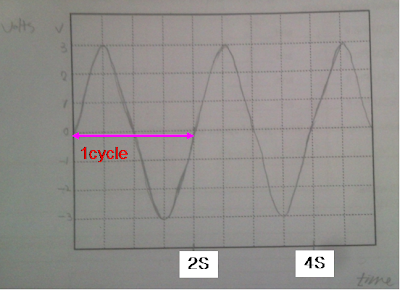
- Digital signal 5v every 2seconds

- Analogue signal 0.5Hz and a maximum of +3v


2. ABS Demonstrators
Left front ECU Pin # 4 and 5
Left rear ECU Pin # 7 and 9
Right front ECU Pin # 11 and 21
Right rear ECU Pin # 24 and 26


Inductive or magnetic sensor
I have used the AC range of a scope.

- Waveform
Left front
 Left rear
 Right front
 Right rear
All the waveforms are not exactly the same. Because there are different gap size between speed sensor and teeth of wheels.
- AC volts
Left front : 3.2v 
Left rear : 4.09v 
Right front : 2.79v
Right rear : 2.89v
I have check the frequency with the graph from the scope.
We can not see both voltage and time from the multi meter. So, the oscilloscope is more accurate.
3. ABS Relays
Powers up the ABS ECU : K39


Powers up the ABS pump : K100
sends power to the ABS HCU solenoids : K38
What is the ECU pin number for the wire that brings in the power to the ABS ECU?
Pin# 1
For the wire that controls the relay for the ABS ECU?
Pin# 15 (ignition switch-ignition on)
Brings in the power to the ABS Pump?
Pin# 13 (from the actuator)
For the wire that controls the relay for the ABS Pump?
Pin# 28(from the ECU)

-Relay waveform

1. Switch on (power on)
2. ECU is earth(triggering)
3. ECU is not triggering
4. Switch off (power off)
- ABS Pump Relay waveform

- Solenoid


On vehicle testing

MAZDA   FAMILIA  1998
The vehicle is safely located on the left.
Checking the ABS systems (Wheel speed sensors, ABS control unit, ABS modulator, ABS pump motor, parking brake switch, brake master cylinder, brake fluid level switch, RPM sensor, foot brake switch, brake booster and main ABS control unit fuse.
1. Wheel speed sensors    Analogue, Magnetic pick up 

- Measuring the air gap (Specification 0.4~1.0mm)
Front Right : 0.406mm Good condition
Front Left : 0.660mm Good condition
Rear Right : 0.406mm Good condition
Rear Left : 0.558mm Good condition

- The waveform of a wheel speed sensor 
This wheel speed sensor has an analogue pattern.

- Frequency
82Hz (idle, the front wheels turn freely on the lift)

- Using a scan tool
I have hooked up the scan tools on the car with using a correct connector of OBD1. Then, I have selected the ABS scan from scan tool's menu.
Checking live data

Checking fault codes
I have found some fault codes and problems from the scan tools.
The ABS warning light was turned on due to I have done test ABS speed sensors with dismantling wheels.
 The ABS warning light have turned off after I have cleared the codes, installed wheels and moved the vehicle. 

Wednesday, 9 November 2011

WS3B A dual trace oscilloscope

1. MAP(analogue voltage) against Injectors(petrol)
Signal Name : MAP/INJECTORS
Volt/division/range : MAP 0.5v/INJECTORS 20v
Time/division/range :MAP 2S/INJECTORS 2mS
Draw the pattern below:
Explain the operation of the sensor or device using the Graph:
(Use arrows at different points, and describe what happens there)

When the engine is running at idle, the sensor signal is produced at around 0.4v. At the same time, fuel is injected consistently for the proper combustion of the engine idling.
1. 13v or 14v Supply voltage flows the injector circuit.
2. Fuel injection time. The fuel is injected the combustion chamber with grounding which is at around 2.5ms at idle and the voltage will be at 0v.
3. Peak Voltage. When the magnetic field is collapsed at the injector coil, the high voltage produces at this point.
4. The peak voltage is recovered normal supply voltage.

When the sudden accelerations and opening throttle are added, the vacuum will decrease at the intake manifold with high voltage signals. At the same time, 2 fuel injection time will increase at the injector pattern.

2. RPM (Hall digital crank or distributor) against Injectors(petrol)
Signal Name : RPM/INJECTORS
Volt/division/range : RPM 5ACv/INJECTORS 20v
Time/division/range : RPM 2mS/INJECTORS 2mS
Draw the pattern below:
Explain the operation of the sensor or device using the Graph:
(Use arrows at different points, and describe what happens there)

When the engine is running at idle, the sensor signal is produced at around 5ACv and its frequency. At the same time, fuel is injected consistently for the proper combustion of the engine idling. As a result, 1 cycle of the RPM sensor is similar to the fuel injection time

When the sudden accelerations and opening throttle are added, the frequency and voltage will increase from the RPM sensor signals. At the same time, the fuel injection time will also increase at the injector pattern.

3. Oxgen sensor against Injectors(petrol)
Signal Name : O2sensor/INJECTORS
Volt/division/range : O2sensor 0.5v/INJECTORS 20v
Time/division/range : O2sensor 5S/INJECTORS 2mS
Draw the pattern below:
Explain the operation of the sensor or device using the Graph:
(Use arrows at different points, and describe what happens there)

When the engine is running at idle, the O2 sensor signal has costant cycles of Lean and Rich which mean that O2 sensor is well operating with its corrct voltage from 0.2 to 0.8v. At the same time, fuel is injected consistently for the proper combustion of the engine idling at around 2.5mS. When the engine is cold or starting, the O2 sensor signal is not correct. So, I waited for O2 sensor's operating temperature then, I got correct results, such as  wave form and signal voltages.

When the sudden accelerations and opening throttle are added, the signal voltage will increase to around 0.8v which means that the fuel is injected the Rich mixture for acceleration and more power. At the same time, the fuel injection time will also increase at the injector pattern, because more fuel comes in the combustion chamber.

4.Injectors(petrol) against Ignition primary
Signal Name : INJECTORS/Ignition Primary
Volt/division/range : INJECTORS 20v /Ignition Primary 20v
Time/division/range : INJECTORS 10mS/Ignition Primary 20mS
Draw the pattern below:
Explain the operation of the sensor or device using the Graph:
(Use arrows at different points, and describe what happens there)

When the engine is running at idle, the ignition primary has constant frequency. At the same time, fuel is injected consistently for the proper combustion of the engine idling.
From the ingition Primary
1. Supply voltage of 13.6v
2. Dwell time : This is where the coil is actually turned on by the vehicle's control module. The coil is building up a strong magnetic field to spark the spark plug during this part of the pattern.
3. Peak voltage : The coil's earth is removed and the magnetic field or flux collapses across the coils 250 to 350 primary windings, which in turn induces a voltage of 150 to 350 volts.
4.Isolation : This is the part where the coil is turned off and the magnecit field that the coil has generated is now collapsing. You can get an idea what shape your coil is in by watching the isolations just after the spark plug is done firing.
If there are fewer than four isolations at this part of the pattern then there could be some shorting in the coil.


When the sudden accelerations and opening throttle are added, the frequency of the Ignition Primary will increase. At the same time, the fuel injection time will also goes up at the injector pattern. 

5.Injectors(petrol) against Ignition primary
Signal Name : Ignition Primary Current/Ignition Primary
Volt/division/range : Ignition Primary Current/Ignition Primary 20v
Time/division/range : Ignition Primary Current 20mS/Ignition Primary 20mS
Draw the pattern below:
Explain the operation of the sensor or device using the Graph:
(Use arrows at different points, and describe what happens there)
 When the engine is running at idle, the ignition primary has constant frequency. At the same time, the Ignition Primary Current also has same frequency.
1. no current
2. high current
3. recovered no current
The current switches on as the dwell period starts and rises until the requisite certain amps is achieved within the primary circuit, at which point the current is maintained until it is released at the point of ignition.
When the sudden accelerations and opening throttle are added, the frequency of the Ignition Primary will increase. At the same time, the Ignition Primary Current will also goes up at the Primary Current pattern. As a result, both Ignition Primary and the Ignition Primary Current frequencies have same patterns.


Reference by http://www.picoauto.com/automotivetopics/primary.html

WS3 Oscilloscope Patterns to Capture

1. Throttle Position Sensor (TPS)
Signal Name : TPS

Volt/division/range : 2 v
Time/division/range : 500 ms
Trigger notes
Probe used : A black probe of the lab scope is touched the earth and a red probe is connected the TPS voltage on the signal panel.
Draw the pattern below:

Explain the operation of the sensor or device using the Graph:
(Use arrows at different points, and describe what happens there)

Position 1 : When the throttle was closed, the voltage was at 0.407 v.
Position 2 : The voltage increased to 3.796 v when the throttle was opening.
Position 3 : The voltage was the highest at 3.796v while the throttle was widely opened.
Position 4 : When the throttle was closing, the voltage dropped to 0.407 v which is same as position 1 value with the completely closed throttle position.

2. Vacuum sensor
Signal Name : Vacuum sensor

Volt/division/range : 1 v


Time/division/range : 1 s


Trigger notes

Probe used : A black probe of the lab scope is touched the earth and a red probe is connected the vacuum sensor voltage on the signal panel.

Draw the pattern below:

Explain the operation of the sensor or device using the Graph:
(Use arrows at different points, and describe what happens there)

From the vacuum sensor, when the engine is idling, the manifold vacuum is highly produced and the sensor creates lower voltage at 1.386 v, at position 1. When the acceleration goes up, manifold vacuum is lower with higher voltage of 3.431 v, at position 2. On the other hand, form deceleration, the manifold vacuum increases again with lower voltage just under 1.386 v. This is due to the throttle body closed, the engine decelerates which creates a lower pressure and higher vacuum at position 3 and 4. I can see the vacuum stability at position 5 which back to its original voltage at idling.

3. Air Temperature Sensor

Signal Name : Air Temperature Sensor

Volt/division/range : 1 v
Time/division/range : 5 s
Trigger notes

Probe used : A black probe of the lab scope is touched the earth and a red probe is connected the air temperature sensor voltage on the signal panel.
Draw the pattern below:

Explain the operation of the sensor or device using the Graph:
(Use arrows at different points, and describe what happens there)

At position 1, the air temperature sensor produces at 1.014 v when the engine is running with normal air temperature. And then, when the heat is added by an heat gun in the intake air, the voltage decreased gradually to 0.832 v, at position 2. When the heat gun is turned off, the voltage increased gradually to near 1.014 due to cool intake air, at point 3. As a result, the air temperature sensor creates higher voltages when the air is cold. On the other hand, when the air is hot, the sensor creates lower voltages.


4. Injector
Signal Name : Injector
Volt/division/range : 20 v

Time/division/range : 5 ms

Trigger notes

Probe used : A black probe of the lab scope is touched the earth and a red probe is connected the injectors voltage on the signal panel.

Draw the pattern below:

Explain the operation of the sensor or device using the Graph:
(Use arrows at different points, and describe what happens there)

The engine is idling. At position 1, 13 v is supplied for injector's operation. When the ECU is grounded, the injector with the generation of magnetic field is opened for around 3ms of fuel injection and the the voltage decreased to almost 0 v, at position 2. At position 3, when the ECU gives injector's switching for cutting the fuel injection, the magnetic field is collapsed with peak voltage. And then, the voltage goes back to the original state at around 13 v, at position 4.  


5. RPM Sensor
Signal Name : cam position sensor and crank position sensor
Volt/division/range : A=2 v (cam), B=5 v(crank)
Time/division/range : 20 ms

Trigger notes

Probe used : A black probe of the lab scope is touched the earth and a red probe (A) is connected the cam signal and another red probe (B) is touched the crank signal on the signal panel.

Draw the pattern below:
Explain the operation of the sensor or device using the Graph:
(Use arrows at different points, and describe what happens there)
A= Cam position sensor, B= Crank position sensor
A good magnetic crank position sensor should produce an alternating current(AC) when the engine is cranked. Higher RPM produces higher voltage and frequency also increases. Defective crank and cam sensors voltage to low. So proper output voltage is critical for appropriate engine operation.

Tuesday, 8 November 2011

WS5 Scan Tool Diagnostics

 NISSAN   Pualsar  1991
(Course: using a Scan Tool that communicates to the engine you want to test.)
Warning: Be careful working around engines and exercise caution to avoid injury.
1. Scan Tool Data


1.1 Find a vehicle which is appropriate for the scan tool. 

1.2 Connect the scanner, power it on, follow the instructions and input the correct vehicle information it asks for so you can view the data.

1.3 Find the data for the information listed on the next page. Turn engine on to idle. Fill in the letters used to label the information and the value of that data. (For example, engine load information may be found under MAP, with a value of 3.6, listed in volts) Note: not all vehicles will support all information, just find as much as you can. If the engine won’t run, input the information with the key on, engine off.


Engine Load(how much air comes in)
MAF  1 v
Engine RPM
RPM  825 RPM
Throttle angle
TPS(idling)  0.48 v
Engine coolant temperature
ECT  93 ℃
Fuel Injection Opening pulse
2.4 ms (idling)
Vehicle Speed
0  km/h
Idle control
IACV  52 %
Ignition timing
15 BTDC
* The O2 Sensor did not respond with any voltages due to the O2 sensor was damaged with its visual inspection(bending damage) 

2. Trouble Codes or Fault Codes
2.1 Find where the Codes are listed 
2.2 Record any codes, and what system and condition they describe in the chart below (Example: might be code number 21, for Throttle Position Sensor, signal voltage too low) If there are no codes listed, put “none”.
NONE

3 Lecturer put in Fault 
3.1 Find your lecturer and have him create a fault under the hood (don’t look)
 
4 Record New Codes
4.1 Look up the codes now in the scan tool
4.2 Record the codes in the chart below. Also record what system is affected, and what condition is described.


11 CAM Position Sensor  :  The engine is not running.
12 MAF : Idling rough and the engine is turned off.
21 Ignition Primary : No engine starting.

5 Find What Data Has Changed
5.1 Look through the scan tool data to see what PIDs (Parameter Identification of system voltages) have changed. Which readings don’t make sense or don’t read what you would expect. Concentrate on the PIDs related to the codes.
5.2 Record the PIDs that have changed below:

Idle  RPM  560~700 RPM
Idle Air Control Valve  IACV  30%
Injection Pulse  2.9 ms
MAF 0 v


6 Visual Inspection to find fault
6.1 Do a visual inspection under the hood to find where the problem is. Use information from the code to know where to look for the problem and what type of problem to look for.
Describe problem you found:

The vacuum sensor(MAF) was disconnected. As a result, the engine idle was rough and the engine was turned off. When I checked the parameter identification of the scan tool, it was changed, such as RPM, IACV, Injection Pulse and MAF sensor signal. 

7 Repair fault
7.1 Plug back in the connector, or repair problem found
7.2 Describe what you did:

I have reconnected the vacuum sensor connector and then restarted the engine. The engine runs well with out any problems.


8 Recheck Data PIDs
8.1 Recheck the data with the scan tool
8.2 Record the voltages for the PIDs related to the problem, to confirm they are back to normal
The engine was recovered normal conditionsIdle RPM  800 RPM

Idle Air Control Valve IACV  52%
Injection Pulse 2.4 ms
MAF 0.98 v


9 Clear Codes
Describe what you did to clear codes:

I made a disconnection of the negative terminal or the engine main fuse for 30 seconds.
From the scan tool, I choose the clear codes of scan tool menu then I have deleted all fault codes.

10 Recheck for codes and record codes in system now:

When I recheck the codes from selecting scan menu, there were no trouble codes on the screen.


11 Discuss the importance live data when fault finding

It shows the state of the sensors and actuators from the live data values, so I can find the problems easily.

12 Explain the need for parameters when checking live data

when the fault is resolved, the live data will be rechecked with its parameters then the data should be compared to fault data.


13 Discuss how a scan tool can aid you when fault finding

I can find the fault easily and although the vehicle is old or new, I can also check the state of a vehicle with various information.

Wednesday, 2 November 2011

WS7 Exhaust Gas Analysis (Petrol only)


HONDA  INTEGRA  1994

Exhaust Analyser should be warmed up and recently calibrated. When it’s time to start taking tailpipe readings, put the analyser probe into the tailpipe and install exhaust tube over probe to capture exhaust fumes. Make sure there is adequate ventilation.

Note: make sure you fill out the “means: ............. segment to explain what that gas reading means. Example, if you are measuring HC, which shows us about misfire in the engine, and you had a low number like 28 ppm, you would say “shows low amount of misfire”, or “most of the fuel is being burnt.” But if the HC was high, like 340 ppm, you might say “There is a high amount of misfire” or “not all the fuel is being burnt.”

1. With the analyser probe sensing normal air, what are the Four Gas readings? Record the amount and then what it means:

CO  0% means:  show rich conditions
HC  7ppm means: higher HC means that unburn fuel remains in the exhaust gases.
CO2  0% means: efficency
O2 20.89% means: lean mixture

2. Start the engine idling cold, and record the Four Gas readings:
Explain what is happening within the engine referring to the four gases:      
CO 0.734%   HC 471ppm   CO2 13.92%   O2 0.64%

When the engine starts with cold idle conditions, the CO increase to 0.734%. This means that rich mixture enters the combustion chamber. The HC also goes up significantly and unburn fuel remains in the exhaust gases. The CO2(efficency) is low and the O2 is high from the inactive catalytic converter.

3. When the engine has warmed up, record the Four Gas readings:
Explain what is happening within the engine referring to the four gases:
 
CO 0.65%   HC 347ppm   CO2 13.54%   O2 1.7%

When the engine is fully warmed up, the CO and HC slightly decrease. This means that ideal mixture enters the combustion chamber. The CO2(efficency) is high and the O2 is high. As a result, the catalytic convertor does not well operates for cleaning the emissions. If the catalytic convertor is good, the HC and CO will drop significantly.
4. Run the warm engine at 2500 RPM, record the Four Gas readings:
Explain what is happening within the engine referring to the four gases:        
CO 0.01%   HC 29ppm   CO2 14.93%   O2 0.17%

When the warm engine is run at 2500 rpm, the CO and HC would be more produced than the engine idling due to higher rpm with more emissions. However, the CO2 increased and O2 are decreased compare to idling condition.

5. At idle, run the mixture rich with extra propane, LPG, or carburettor cleaner, and record the Four Gas readings:
Explain what is happening within the engine referring to the four gases: 

CO 11.46%   HC 453ppm   CO2 7.77%   O2 0.737% 

At idle, I made a disconnection of the vacuum sensor for the rich condition. Then, the engine idle is rough with 0.737 lambda value. The CO increases to 11.46% which means the state of rich mixture. The unburn fuel is more produced due to more fuel injection.

6. At idle, create a lean condition with an air leak or vacuum leak, record the Four Gas readings:
Explain what is happening within the engine referring to the four gases:

CO 0.001%   HC 79ppm   CO2 12.77%   O2 3.20% 
At idle, I made a disconnection of the PCV valve for the lean condition. The CO recovers the nomal condition. The unburn fuel decreased to 79ppm. The CO2(efficency) and the O2 increases significantly which means the state of lean mixture.

7. Accelerate the engine, by blipping the throttle a few times (don’t rev too high anddamage the engine), and watch how the gas readings change. Record the Four Gas readings when the CO is highest:
Explain what is happening within the engine referring to the four gases:

CO 4%   HC 500ppm   CO2 8.7%   O2 6.54%

From the sudden acceleration, the rich mixture is supplied into the combustion chamber. The CO and HC rise. The CO2(efficency) is reduced but the O2 increases sigificantly due to more fuel injection with more intake air.

8. Disconnect one spark plug wire, ground it with a jumper wire, then record the Four Gas readings as the engine idles:
Explain what is happening within the engine referring to the four gases:

CO 1.29%   HC 4740ppm   CO2 10.07%   O2 6%
When the misfire is produced in a cylinder, the HC increases dramatically because the unburn fuel is created by the misfired cylinder. The O2 is also produced more from the air/fuel mixture of the misfired cylinder compare to the normal condition.

9. If you can get to it, disconnect the injector harness connector from one injector on an engine that has one injector for every cylinder: Record the Four Gas readings as the engine idles:
Explain what is happening within the engine referring to the four gases:

CO 0.015%   HC 611ppm   CO2 9.65%   O2 5.84%

When the injector is disconnected, the HC is normal because the fuel does not injects into the intake port. However, the O2 increases due to the air is still supplied into the combustion chamber.

10. Optional: Make other changes to the engine at idle, such as turning on the air conditioning or rocking the steering wheel. Note the change you made:
Explain what is happening within the engine referring to the four gases:

CO 0.029%   HC 33ppm   CO2 14.82%   O2 0.36%

Overall, the emission is clean with proper values. However, when loads (air conditioning and rocking the steering wheel) are added, the rpm will go up. As a result , the CO and HC increase slightly with the rich condition. 
Return the vehicle to good condition and proper adjustment.
11. Explain the different readings you would get from a vehicle with a catalytic converter and a vehicle without one and why?

I would get the differnt readings. If the vehicle does not have a catalytic converter the emission will be exhausted without any filtering. The catalytic converter helps reducing emissions with its chemical actions.

12. Explain what light off point means and what happens?
When the temperature is hot enugh, the catalytic converter will clean the emissions with its operating temperature.
13. On lambda, 02 sensors why do they have 1,2,3,4 or 5 wires and what do these extra wires do?
From two white heater positive and negative, the O2 sensor works correctly and increases responses with operating temperature when the engine starts with cold conditions. The black wire is a snesor signal positive which gives the state of exhaust gases to the ECU. The gray wire is a sensor signal earth.